Product Description
The PDG-M750C/PDG-M751C is a high-performance 4G Cat1 DTU product that supports mobile 4G, China Unicom 4G, and China Telecom 4G SIM cards. It is designed with high data transmission rates, low latency, and wireless communication as its core features, enabling swift resolution of wireless communication solutions in various application scenarios.
It supports TCP/UDP/HTTP/MQTT/DNS/RNDIS/NTP protocols, enables connections to various cloud servers such as XiaoZhouOpen, Alibaba Cloud, Baidu Cloud, and OneNET. It also facilitates TCP/UDP/HTTP/MQTT data transparent transmission, USB wireless network card support, automatic scheduled data collection tasks, base station positioning, customization of heartbeat and registration packet data, configuration of parameters through host computer/AT commands/SMS/transparent commands, and supports both RS232 and RS485 serial interfaces. It can be widely used in wireless data transmission, power industry, industrial control, water conservancy industry, environmental protection industry, agricultural applications, data collection systems, and smart homes, among many other fields.
Explanation
The PDG-M750C is a small package module with pin headers. The information in this document is also applicable to this product. The PDG-M750C operates at TTL voltage level.
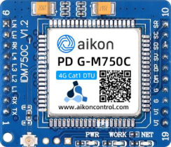
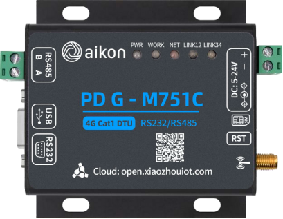
Key Features
✓ 4G Cat1 universal network compatibility, supporting mobile 4G, China Unicom 4G, and China Telecom 4G. ✓ Multiple working modes supported: NET/HTTP/MQTT/RNDIS. ✓ Integration with various cloud server platforms: XiaoZhou Open/Alibaba Cloud/Baidu Cloud/OneNET. ✓ Wireless internet access supported through RNDIS protocol. ✓ Automatic data collection task functionality, supporting up to 5 commands. ✓ Simultaneous online connectivity for 4 network connections, supporting TCP long connections, TCP short connections, and UDP protocol. ✓ Dynamic domain name and IP address access supported. ✓ Registration packet/heartbeat packet functionality. ✓ GET and POST request support in HTTP mode, with configurable request header parameters. ✓ Multiple configuration methods supported: AT commands, SMS configuration, transparent transmission commands, and host computer. ✓ Automatic reconnection, disconnection monitoring, built-in watchdog, ensuring stability and reliability. ✓ Serial port time and length packaging mechanism, with 10KB serial data cache per connection. ✓ Base station positioning supported (limited free trial, contact us for purchasing the service). ✓ Real-time time query functionality. ✓ English SMS sending supported through AT commands. ✓ Multiple firmware upgrade modes supported: local upgrade, remote upgrade, and automatic firmware updates. ✓ Wide voltage power supply range of 5~24V, suitable for various scenarios.
Characteristic parameters
Network parameters
| Parameter | Information |
|---|---|
| Frequency Band | LTE-TDD: B34/B38/B39/B40/B41 LTE-FDD: B1/B3/B5/B8 |
| Transmission Rate | LTE-TDD: Downlink speed 7.5Mbps, Uplink speed 1Mbps LTE-FDD: Downlink speed 10Mbps, Uplink speed 5Mbps |
| Transmit Power | LTE-TDD: Class3 (23dBm±2dB) LTE-FDD: Class3 (23dBm±2dB) |
Hardware specifications
| Parameter | Information |
|---|---|
| Operating Voltage | DC: 5V-24V, Recommended Power: 12V@1A |
| Operating Current | 300mA (max) @ 12V |
| Operating Temperature | -25°C to 75°C |
| Storage Temperature | -45°C to 90°C |
| Communication Interface | PDG-M750C: Serial Interface: TTL Level, Baud Rate Range: 2400-921600 PDG-M751C: Serial Interface: RS232/RS485, Baud Rate Range: 2400-921600 |
| Serial Buffer | Network Transparent Mode: 4*10K bytes (10K buffer per connection) Other Modes: 10K bytes |
| Antenna Interface | PDG-M750C: IPEX Generation 1 PDG-M751C: Full Band Antenna (SMA External Thread Inner Hole) |
| SIM Card | Supports SIM Card Voltage: 1.8V/3.0V PDG-M750C: SIM Card Size: Length 15mm * Width 12mm (Micro SIM Card/Mini SIM Card) PDG-M751C: SIM Card Size: Length 25mm * Width 15mm (Standard SIM Card/Full-size SIM Card) |
| Dimensions | PDG-M750C: 40mm * 34.5mm PDG-M751C: 83mm * 83.7mm * 25mm |
Software functionality
| Parameter | Information |
|---|---|
| Configuration Method | Host computer, AT command set, SMS, transparent command |
| Operating Mode | NET, HTTP, MQTT, Alibaba Cloud, Baidu Cloud, OneNET, RNDIS |
| XiaoZhou Open | Supported |
| Data Packages | 1. Heartbeat package: supported 2. Registration package: supported (supports IMEI/ICCID/IMSI/custom data) |
| Automatic Collection Task | Host computer, AT command set, SMS, transparent command |
| Configuration Method | Supported, maximum support for 5 commands |
| Base Station Positioning | Supported (direct output of latitude and longitude data) Limited free usage, contact us to purchase base station positioning service |
| NTP (Network Time Protocol) | Supported |
| SMS Sending | Supported, send English SMS using AT commands |
| Domain Name Resolution | Supported for domain access |
| Domain Access Support | 1. Startup prompt message: supported (customizable startup prompt message) 2. Custom user data: supported (can configure custom data to differentiate different DTUs) |
| Firmware Upgrade | Supported remote/local firmware upgrade/automatic firmware update |
Introduction to Module Resources
Resources for PDG-M750C module.
| Hardware Resources | Description | Remarks |
|---|---|---|
| 1. Module Interface | The module has a total of 19 pins available for users to integrate into their own products. | Note: Only one of the onboard SIM card slot and the external SIM card interface can be used at a time! |
| 2. IPEX Antenna Interface | The module's antenna interface for connecting an external antenna. | IPEX is a first-generation interface. |
| 3. Power Indicator | The module's power indicator (blue). | Constantly on: Module is powered on. Constantly off: Module is powered off. |
| 4. Working Status Indicator | The module's working status indicator (red). | Constantly on: Module is functioning normally. Constantly off: Module is not working. |
| 5. Network Status Indicator | The module's network status indicator (green). | Off: Module is not working. On for 200ms/off for 200ms: Not registered on the network. On for 64ms/off for 2000ms: Registered on the network. On for 64ms/off for 300ms: Data communication status. |
| 6. Micro SIM Interface | The module's onboard SIM card slot. | Supports SIM card size: 12mm*15mm (Micro SIM). Note: Only one of the onboard SIM card slot and the external SIM card interface can be used at a time! |
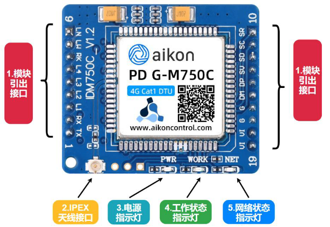
The module only has one Micro SIM interface on the back.
Resources for PDG-M751C module.
| Hardware Resources | Description | Remarks |
|---|---|---|
| 1. Status Indicators | The module provides seven status indicators to indicate the module's operational status. | PWR: Blue WORK: Orange NET: Pink LINK12 and LINK34: Red/Green dual-color |
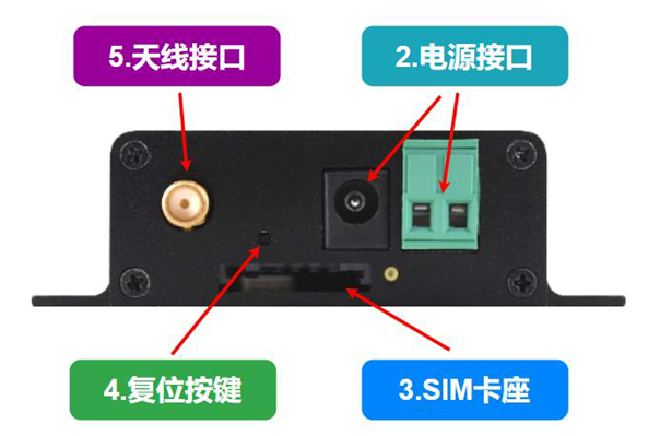
| 2. Power Interface | The module offers two power interfaces: DC050 and KF2EDG-2P. | Among them, DC050 has an inner diameter of 5.5mm and a pin diameter of 2.1mm. |
| 3. SIM Card Slot | Used for inserting a SIM card (standard size). | Note: The standard size of a SIM card is 25mm*15mm. |
| 4. RST Button | Can be used to reset factory parameters or enter firmware upgrade mode. | |
| 5. Antenna Interface | PDG-M751C full-band antenna interface. | SMA external thread inner hole. |
| 6. RS232 Interface | RS232 serial interface. | DR9 female connector. |
| 7. Micro USB Interface | Required for using RNDIS functionality. | |
| 8. RS485 Interface | RS485 serial interface. | KF2EDG-2P interface. |
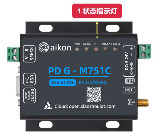
Product front view
Right view of the product

Left view of the product
Status Indicator Explanation
The PDG-M750C module offers seven status indicator pins, which can be used to control LEDs for displaying the module's operational status. These six status indicators are PWR, WORK, NET, LINK1, LINK2, LINK3, and LINK4. The PWR, WORK, and NET indicator lights are already integrated on the module, but the module also provides separate pins for controlling the WORK, NET, LINK1, LINK2, LINK3, and LINK4 status indicators, allowing users to integrate them into their own devices. On the other hand, the PDG-M751C module features seven status indicators: PWR (blue), WORK (orange), NET (pink), LINK12 (dual-color red/green), and LINK34 (dual-color red/green). Below is a description of each indicator.
Status indicators and pin level descriptions of the PDG-M750C module
| Indicator | Description | Note |
|---|---|---|
| Power (PWR) | Power indicator | Steady on: Module powered on Off: Module not powered |
| Working (WORK) | Module operational status indicator | High level (steady on): DTU functioning normally Low level (off): DTU not functioning |
| Network (NET) | Low level (off) | DTU not functioning |
| High level 200ms/Low level 1800ms | Not registered on the network | |
| High level 1800ms/Low level 200ms | Registered on the network | |
| High level 250ms/Low level 250ms | DR9 female interface |
LINK pin voltage status
| Work Mode | Description | LINK Pin Level Status |
|---|---|---|
| TCPLONG (each connection corresponds to a status LED) | Not connected | High level |
| Connecting | Low level for 50ms, high level for 1s | |
| Connection successful | Low level | |
| TCPSHORT (each connection corresponds to a status LED) | Not connected | High level |
| Connection successful | Low level | |
| UDP (each connection corresponds to a status LED) | Not connected | Low level for 50ms, high level for 1s |
| Connection successful | Low level | |
| HTTP GET | LINK1/3 low level during data communication, high level when not in communication | |
| HTTP POST | LINK2/4 low level during data communication, high level when not in communication | |
| MQTT | Not connected | Low level for 50ms, high level for 1s |
| Connection successful | LINK1 low level | |
| Alibaba Cloud | Not connected | Low level for 50ms, high level for 1s |
| Connection successful | LINK1 low level | |
| Baidu Cloud | Not connected | Low level for 50ms, high level for 1s |
| Connection successful | LINK1 low level | |
| OneNET | Not connected | Low level for 50ms, high level for 1s |
| Connection successful | LINK1 low level | |
| RNDIS | LINK1/2/3/4 simultaneously low level for 1s, high level for 1s | |
| Restore to factory settings | Parameters initializing: LINK1/2/3/4 simultaneously low level for 80ms, high level for 50ms. Parameters initialized successfully: LINK1/2/3/4 simultaneously low level | |
| Enter firmware upgrade | LINK1/2/3/4 cycle lighting sequence: 1->2->3->4->1->2->3->4... | |
| Enter network upgrade | LINK1/2 simultaneously low level for 80ms, high level for 50ms |
Explanation of PDG-M751C Module Status Indicator Lights
| Indicator | Description | Status |
|---|---|---|
| PWR | Power Indicator | Constantly lit: Module powered on, Off: Module not powered on |
| WORK | Module Operation Indicator | Constantly lit: Module functioning properly, Off: Module not operating |
| NET | Network Indicator | Off: Module not operating |
| High level for 200ms/Low level for 1800ms | Not registered on the network | |
| High level for 1800ms/Low level for 200ms | Registered on the network, data communication status | |
| High level for 250ms/Low level for 250ms | Data communication status |
LINK status indicator
| Work Mode | Description | Status of LINK Indicator |
|---|---|---|
| TCPLONG (each connection corresponds to one indicator) | Connecting | On for 50ms/Off for 1s |
| Connection successful | Constantly on | |
| TCPSHORT (each connection corresponds to one indicator) | Not connected | Constantly off |
| Connection successful | Constantly on | |
| UDP (each connection corresponds to one indicator) | Not connected | On for 50ms/Off for 1s |
| Connection successful | Constantly on | |
| HTTP GET | Data communication in progress | LEDs 1 and 3 (two green LEDs) constantly on, LEDs off after communication |
| HTTP POST | Data communication in progress | LEDs 2 and 4 (two red LEDs) constantly on, LEDs off after communication |
| MQTT | Not connected | LINK1 (green LED) on for 50ms/Off for 1s |
| Connection successful | LINK1 (green LED) constantly on | |
| Alibaba Cloud | Not connected | LINK1 (green LED) on for 50ms/Off for 1s |
| Connection successful | LINK1 (green LED) constantly on | |
| Baidu Cloud | Not connected | LINK1 (green LED) on for 50ms/Off for 1s |
| Connection successful | LINK1 (green LED) constantly on | |
| OneNET | Not connected | LINK1 (green LED) on for 50ms/Off for 1s |
| Connection successful | LINK1 (green LED) constantly on | |
| RNDIS | All four LINK indicators simultaneously on for 1s/Off for 1s | |
| Restore to factory settings | During initialization, all four LINK indicators blink simultaneously, indicators remain on after parameter reset | |
| Enter firmware upgrade mode | All four LINK indicators blink alternately | |
| Enter network upgrade mode | LINK1 and LINK2 indicators blink rapidly simultaneously |
Instructions for inserting and removing the SIM card
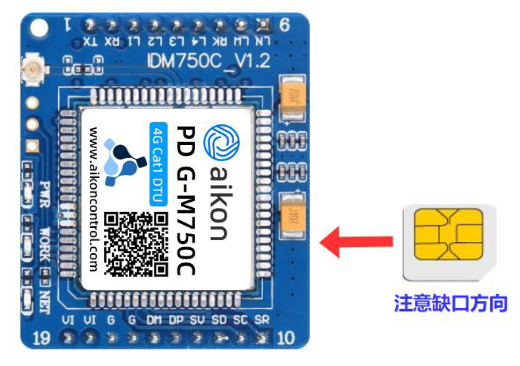
Instructions for placing the SIM card in the PDG-M750C mobile phone
The PDG-M750C product comes with a built-in self-ejecting SIM card slot. To insert the SIM card, simply slide it into the bottom end. When removing the SIM card, gently press on it to automatically eject it. Please refer to the diagram below for the correct orientation when inserting the SIM card. Please note the direction of the SIM card notch.
Instructions for Inserting the PDG-M751C SIM Card
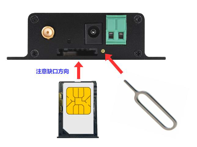
To insert the PDG-M751C SIM card into the card slot, gently push a pointed object into the small hole located as shown in the diagram below to eject it.
When inserting the SIM card, you need to place it into the SIM card tray as shown in the diagram below. Then, insert the SIM card tray into the SIM card slot.
Preparation and Precautions for Use
Important Notes:
- Cat1DTU is a 4G product that supports mobile 4G, China Unicom 4G, and China Telecom 4G SIM cards.
- Please refrain from randomly inserting or removing the SIM card while the DTU is powered on, as it may cause damage to the SIM card.
- Before using the DTU, ensure that the SIM card has sufficient credit, activated data plan, and is not locked. If SMS functionality is required, it needs to be activated.
- During the use of the DTU, the calling function of the SIM card will be disabled.
- The default settings for the serial port are as follows: (Baud rate: 9600) / (Stop bits: 1) / (Data bits: 8) / (Parity: NONE).
- When using the reset button to restore factory settings, wait for the initialization process to complete (indicated by all four lights transitioning from blinking to steady) before disconnecting the power. Failure to do so may result in unsuccessful parameter restoration.
- The RS232 and RS485 serial communication interfaces cannot be used simultaneously.
- When using the DTU, ensure proper installation of the antenna as poor signal reception may affect communication speed.
- When using the DTU, all SMS messages stored in the SIM card will be deleted. It is advised to save important information before usage.
Preparation Before Use, you need to prepare the following resources:
- PDG-M750C or PDG-M751C product.
- A mobile SIM card (compatible with China Mobile, China Unicom, or China Telecom, with available credit and internet access).
- An external power supply (using a 12V/1A adapter).
- A USB to RS232 or USB to 485 serial port tool.
- A full-band antenna (provided as a package when purchasing the product).
Please note that if you encounter the following prompts in the "Preparation before use" section, please follow the instructions provided below:
If the DTU serial port displays the message "Please check SIM Card !!!," it indicates that the DTU has not detected a SIM card. Please refer to section 1.5 for instructions on checking the correct placement of the SIM card.
If the DTU serial port displays the message "Please check CSQ !!!," it suggests that the current signal strength of the DTU is weak. Please verify if the antenna is properly connected.
If the DTU serial port displays the message "Please check GPRS !!!," there may be two potential issues: whether the SIM card has outstanding fees or if the antenna is properly connected.
 XiaoZhou document