PD MDC Product Description
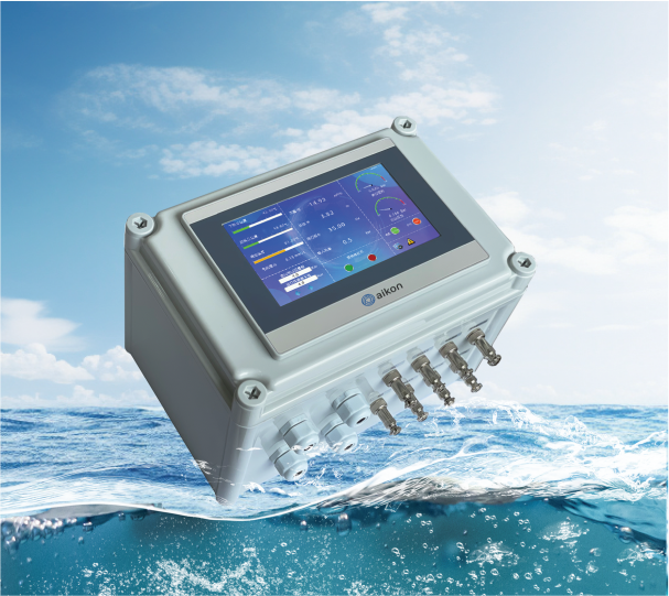
XiaoZhou has launched a new Internet of Things (IoT) product called PD MDC. PD MDC is an innovative IoT product designed to monitor relevant data and provide feedback on operational efficiency and health status. Whether it is household appliances or industrial machinery, PD MDC can continuously monitor their operational status in real-time and provide accurate data analysis.
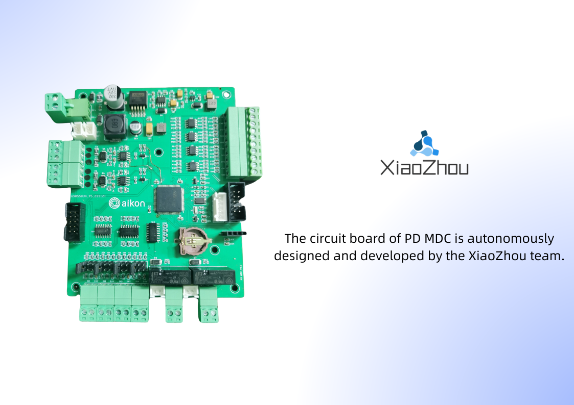
Motherboard
- Photographs of the motherboard
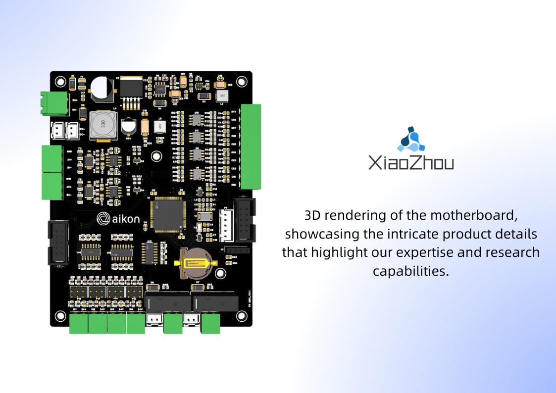
- 3D rendering of the motherboard
Product Overview
This product operates on a DC24V power supply and features one main power interface and two DC24V interfaces for expansion. It is equipped with two independent RS485 communication interfaces and one interface that supports various DTU modules. Additionally, it has 8 analog input interfaces, 4 digital input interfaces, and 2 digital output interfaces. The DTU module interface on a single board can only accommodate one module at a time and cannot simultaneously connect multiple different modules. The analog input interfaces are designed for 4-20mA current type, while the digital output interfaces provide relay outputs. Furthermore, it offers a DC24V indicator light interface synchronized with the relays.
- Product appearance
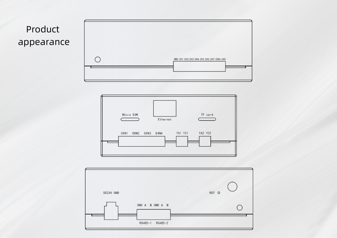
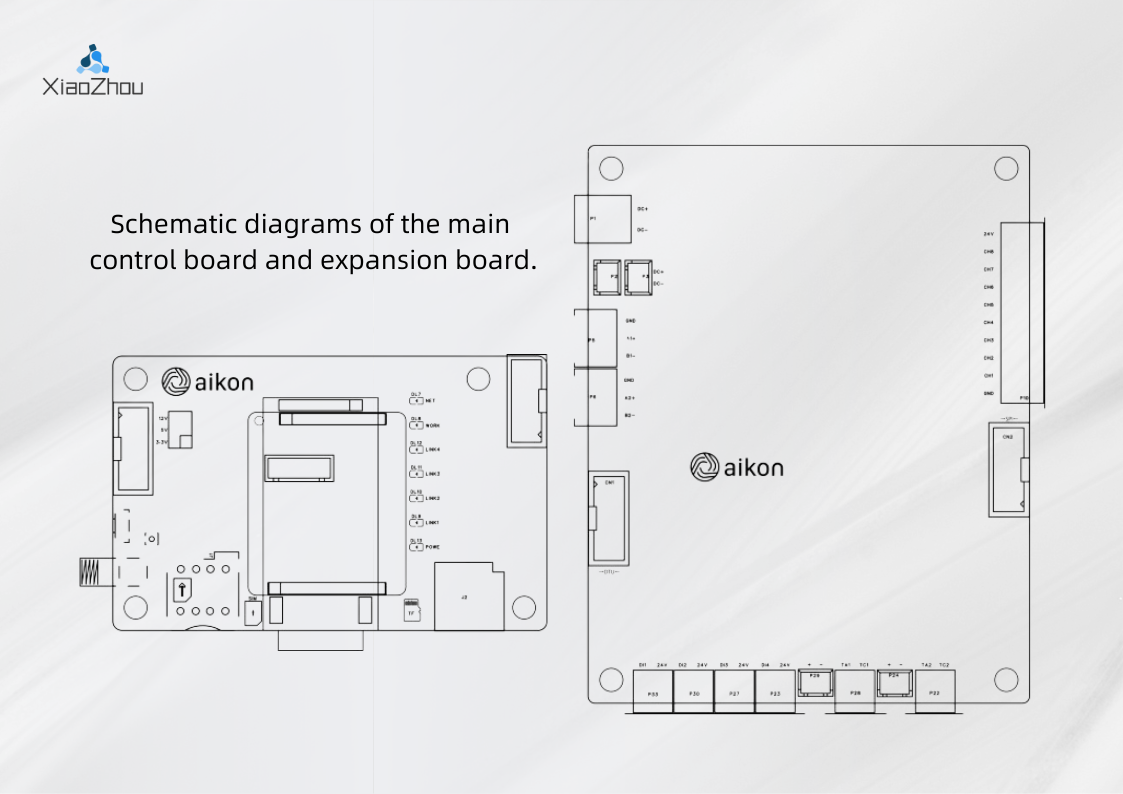
- Schematic diagrams of the main control board and expansion board
Product specifications
| Module | Parameters | Values |
|---|---|---|
| Hardware Parameters | Network Access | Ethernet or 4G |
| Serial Port | RS485 | |
| Sensor Interface | 8 channels, GX12 interface 2P/3P | |
| Electrical Specifications | Rated Voltage | DC24V |
| Allowable Power Loss | <3ms | |
| Environmental Requirements | Operating Temperature | -10~60°C |
| Storage Temperature | -20~70°C | |
| Protection Level | IP65 | |
| Cooling Method | Natural air cooling | |
| Appearance Material | Dimensions | 280mm x 190mm x 135mm |
| Total Weight | Approximately 2kg | |
| Material | ABS plastic | |
| VPN | Not supported | |
| Software Parameters | Data Monitoring | Up to 500 points |
| Alarm Notifications | Support email, mobile, SMS, WeChat, DingTalk, Enterprise WeChat, Telegram notifications | |
| Historical Data | 50 points |
Power supply
P1 is a 5.08mm pluggable terminal interface for DC 24V power input. P2 and P3 are XH2.54 interfaces, which can provide 24V power output for other expansion boards.
DANGER
Avoid directly connecting the P2 and P3 interfaces to the switch power supply.
RS485 communication serial port
The PD MDC device features two RS485 serial ports, namely Port P5 and Port P6, which operate using the standard Modbus-RTU protocol. The PD MDC device offers two operational modes: slave mode and relay mode. In slave mode, both Port 1 and Port 2 can be connected to a master device for read and write operations on the PD MDC device. In relay mode, Port 1 can be connected to a master device, while Port 2 can be connected to multiple slave devices. In this mode, the PD MDC's DTU module and the master device connected to Port 1 can simultaneously read and write data from the PD MDC itself, as well as from all the slave devices connected to Port 2.
Digital input interface (binary input interface)
The digital quantity input interface can be used as a regular digital quantity input terminal. It can also be connected to sensors such as PTC and electrodes to detect changes in resistance. The PD MDC provides three selectable resistance values, which can be chosen using jumper caps. These values are 4kΩ, 10kΩ, and 30kΩ. Taking 30kΩ as an example, when the resistance between interface DI1 and 24V output is greater than 30kΩ, the digital quantity interface is considered as open. When the resistance is less than 30kΩ, the digital quantity interface is considered as closed. The three resistance values are primarily designed for internal or external sensors in water pumps. For instance, the 4kΩ value is used to determine if the motor PTC temperature is too high, while the 10kΩ or 30kΩ values are used to detect the presence of water leakage in the float or electrode environment.
Digital output interface (binary output interface)
The digital quantity output interface is a normally open relay output, with each one providing a DC24V output synchronized with the relay. It can be used to connect devices such as indicator lights and buzzers.
The load capacity of the relay contacts is 5A at 250V AC/5A at 30V DC.
Analog data acquisition interface
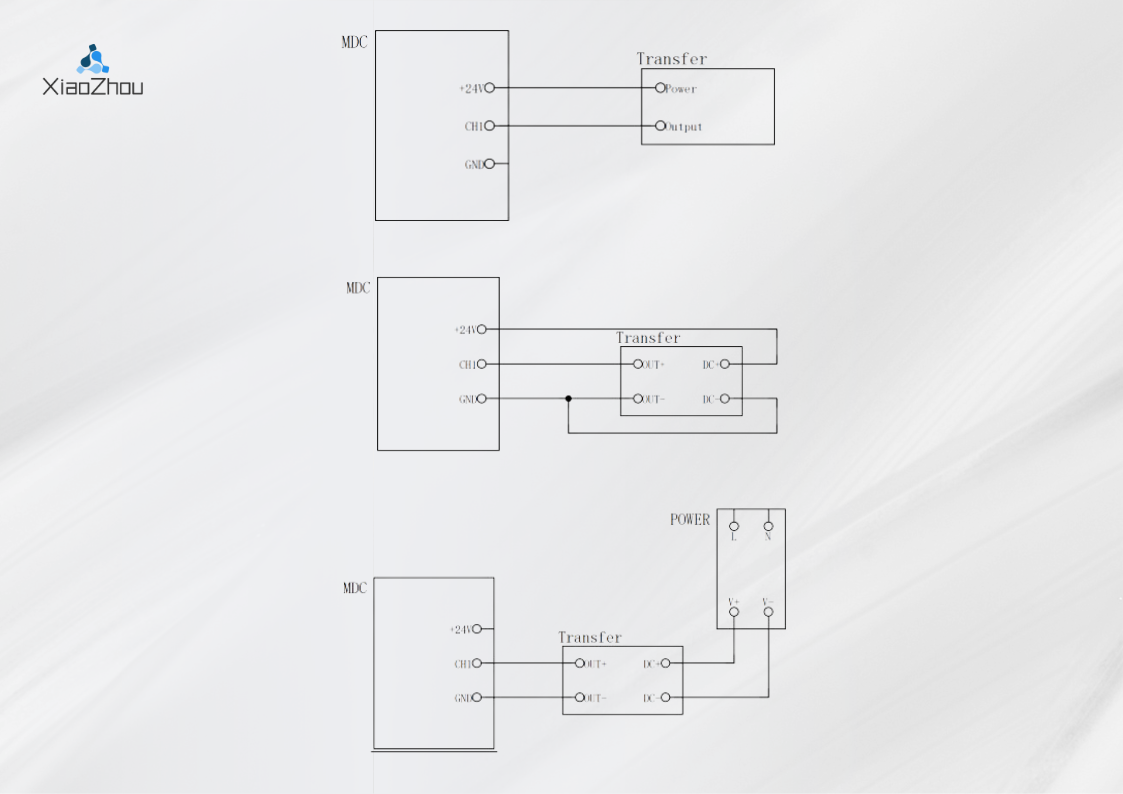
All eight analog interfaces are configured to receive 4-20mA signals. Below, I have provided several wiring configurations for sensor connections, using CH1 as an example, for your reference.
Expansion board
The expansion board includes a Data Terminal Unit (DTU) module and a TF card module.
Based on the connectivity options, there are two available expansion boards to choose from: DTU-4G and DTU-LAN.
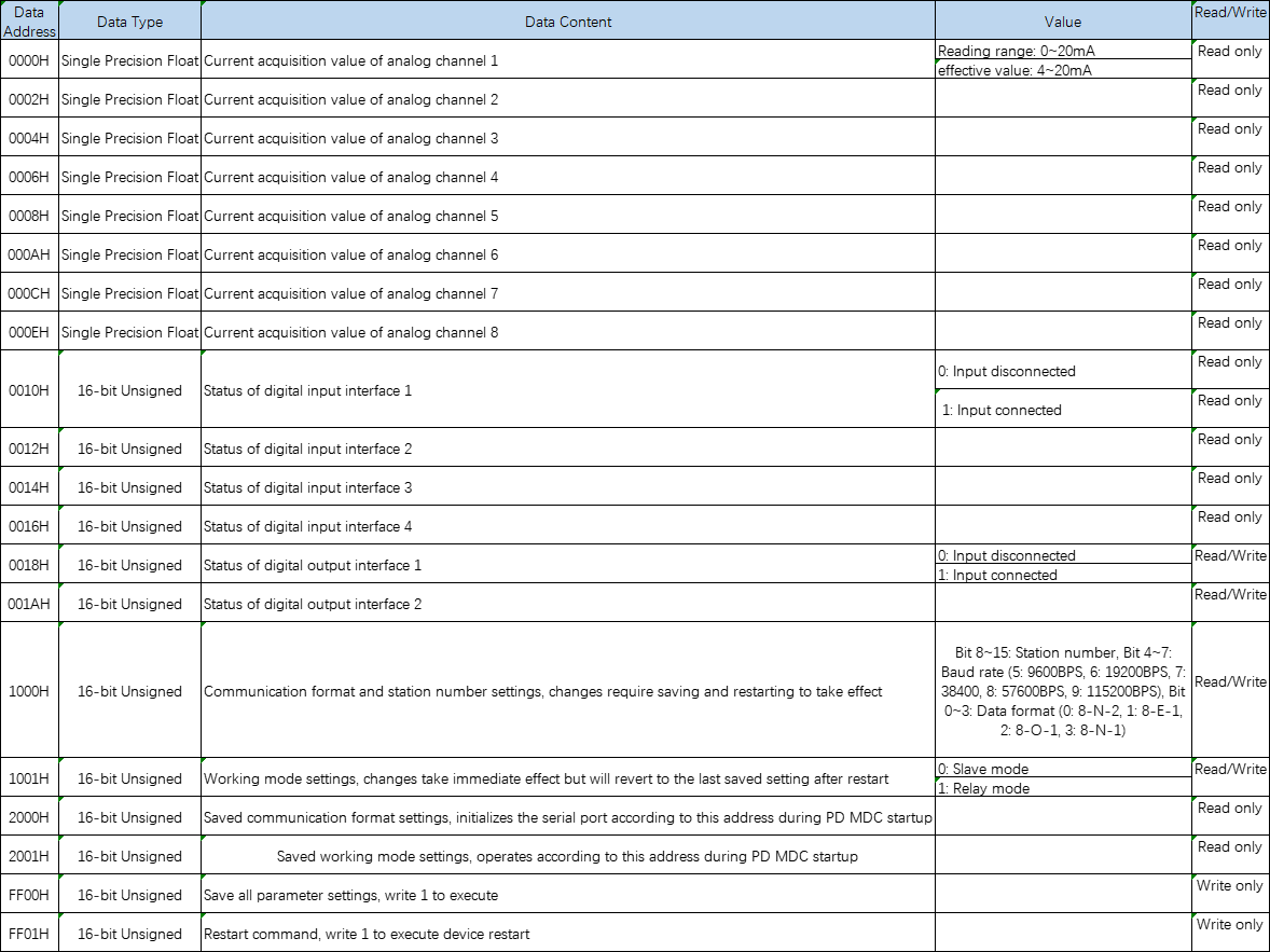
Address Form
Modbus communication protocol
The PD MDC device offers two RS485 communication interfaces, utilizing the internationally recognized Modbus-RTU communication protocol.
Agreement content
The Modbus-RTU serial communication protocol defines the content and format of asynchronous transmission frames in serial communication. This includes the formats of the master polling and broadcast frames, as well as the response frames from the slave devices. The frame content organized by the master includes the slave address (or broadcast address), the command execution, data, and error checking. The slave's response follows the same structure, including acknowledgment of action, returned data, and error checking. If the slave encounters an error while receiving a frame or is unable to fulfill the requested action from the master, it will generate a fault message as a response to provide feedback to the master.
Method of application
The PD MDC is connected to a "single master multiple slave" PC/PLC control network with an RS485 bus. Additionally, the communication bus network connection may vary depending on the PD MDC's operating mode. For more details, please refer to the hardware section of this manual.
Bus architecture
- Interface: RS485 hardware interface.
- Transmission: Asynchronous serial, half-duplex transmission. Only one device, either the host or the slave, can send data at a given time while the other can only receive data. Data is transmitted in the form of messages, frame by frame, in the process of serial asynchronous communication.
- Topology: Single host, multiple slave system. The range for setting slave addresses is from 1 to 247, with 0 being the broadcast communication address. The slave addresses in the network must be unique, as this is the foundation for ensuring Modbus serial communication.
Agreement Explanation
In a Modbus-RTU communication network, only one device (referred to as the "master") is capable of establishing the protocol (referred to as "query/command"). Other devices (referred to as "slaves") can only respond to the master's "query/command" by providing data or performing corresponding actions based on the master's instructions. The master in this context can be a personal computer (PC), industrial control equipment, or a programmable logic controller (PLC), while the slave refers to the PD MDC. The master can communicate with individual slaves or broadcast messages to all the subordinate slaves. For individually addressed master queries/commands, the slaves are required to provide a response, while for broadcast messages from the master, the slaves do not need to provide a response.
When operating in relay mode, the PD MDC identifies the commands received through its serial port 1 and DTU module. If the command is intended for the PD MDC itself, it responds accordingly. If it is not intended for the PD MDC, the command is forwarded through serial port 2. In this case, within the serial port 2's bus network, the PD MDC can be considered as the master. When the subordinate devices respond, the PD MDC forwards the response received through serial port 2 via serial port 1 or sends it to the DTU module.
The PD MDC utilizes the Modbus-RTU protocol, where a new message transmission must begin with a minimum silent period of 3.5 bytes as a start. In a network where the transmission rate is calculated in baud rate, the 3.5-byte transmission time can be easily determined (as shown in the diagram below: T1-T2-T3-T4). The first field transmitted is the device address, and the permissible transmission characters are hexadecimal 0...9, A...F. Network devices continuously monitor the network bus, including the pause interval time. Once the first field (address field) is received, each network device acknowledges that byte. As the last transmission byte is completed, there is another interval of at least 3.5 bytes of transmission time to indicate the end of the frame. After this, a new frame will begin. The entire message frame must be transmitted as a continuous stream. If there is a pause time exceeding 1.5 character times before the frame is completed, the receiving device will discard the incomplete message and assume the next byte is the address field of a new message. Similarly, if a new message starts within less than 3.5 character times after the previous message, the receiving device will consider it as an extension of the previous message. This will result in an error since the value of the final CRC field cannot be correct.

- The standard format of RTU frames.
| Frame Header START | T1-T2-T3-T4 (3.5 character time) |
|---|---|
| Slave Address ADR | Communication Address: 1-247 |
| Command Code CMD | 03: Read Slave Parameters; 06: Write Slave Parameters |
| Data Content DATA (N-1) | Information Content: Function Code Parameter Address, Function Code Parameter Count, Function Code Parameter Value, etc. |
| Data Content DATA (N-2) | |
| ... ... | |
| Data Content DATA0 | |
| CRC Check High Byte | Check Value: CRC Value |
| CRC Check Low Byte | |
| END | T1-T2-T3-T4 (3.5 character time) |
- Command (command instruction) and Data (data description)
Command code: 03H. Read N words. For example: Read the analog data of CH1 from the PD MDC with slave address 01. The data length is 1 single-precision floating-point (2 words).
| Instruction | Opcode |
|---|---|
| Address | 01H |
| Command | 03H |
| High byte of starting address | 00H |
| Low byte of starting address | 00H |
| High byte of register count | 00H |
| Low byte of register count | 02H |
| Low byte of CRC CHK | CRC CHK value to be calculated |
| High byte of CRC CHK |
- The machine responds to the information.
| Instruction | Opcode |
|---|---|
| ADR | 01H |
| CMD | 03H |
| Byte Count | 04H |
| Data Section | 00H |
| 00H | |
| 00H | |
| 00H | |
| CRC CHK Low | To be calculated |
| CRC CHK High |
Instruction code: 06H Write a word, for example: write 1 (01H) to the address 1001H of PD MDC at slave address 02.
| Instruction | Opcode |
|---|---|
| Address | 02H |
| Command | 03H |
| High Address | 10H |
| Low Address | 01H |
| High Value | 00H |
| Low Value | 01H |
| Low CRC CHK | CRC CHK value to be calculated |
| High CRC CHK |
- The machine responds to the information.
| Instruction | Opcode |
|---|---|
| Address | 02H |
| Command | 03H |
| High Address | 10H |
| Low Address | 01H |
| High Value | 00H |
| Low Value | 01H |
| Low CRC CHK | CRC CHK value to be calculated |
| High CRC CHK |
Application Examples
Monitoring of the air conditioning cooling pump unit.
By connecting temperature, pressure, and other sensors, the real-time operating conditions of the air conditioning cooling pump unit are collected. The data is then uploaded to the cloud platform, and after analyzing the data, appropriate energy-saving solutions are provided.
Soft start pump group fault protection
Connect PTC, electrodes, float, and PT100 sensor to detect the status of the water pump. Trigger protective actions in case of motor overheating, leakage, or other faults, and display the current external faults on the HMI. The protective temperature for PT100 can be set through the HMI. Optionally, the project can be equipped with a DTU module to connect to a cloud platform, enabling remote monitoring and fault information notifications.
 XiaoZhou document